In ultrasonic non-destructive testing (NDT), echo signals acquired on the screen are represented as points and lines in a 2D space. Knowing exactly where these signals are located in relation to the physical weld cross-section is critical to the accuracy of the evaluation.
DSVision’s Weld Profile feature moves beyond simple geometric illustrations, projecting a precise real-time model of the actual weld geometry directly onto the scan view (such as S-scans). This “Weld Overlay” allows inspectors to immediately determine whether a detected signal lies within the weld bead volume, near the Heat-Affected Zone (HAZ), or at the root of the weld joint.
1. 2D & 3D Flexible Weld Type Configuration
DSVision supports advanced modeling options to accurately mirror a wide variety of industrial weld configurations and bevel specifications.
① Weld Type Support & UI Setup
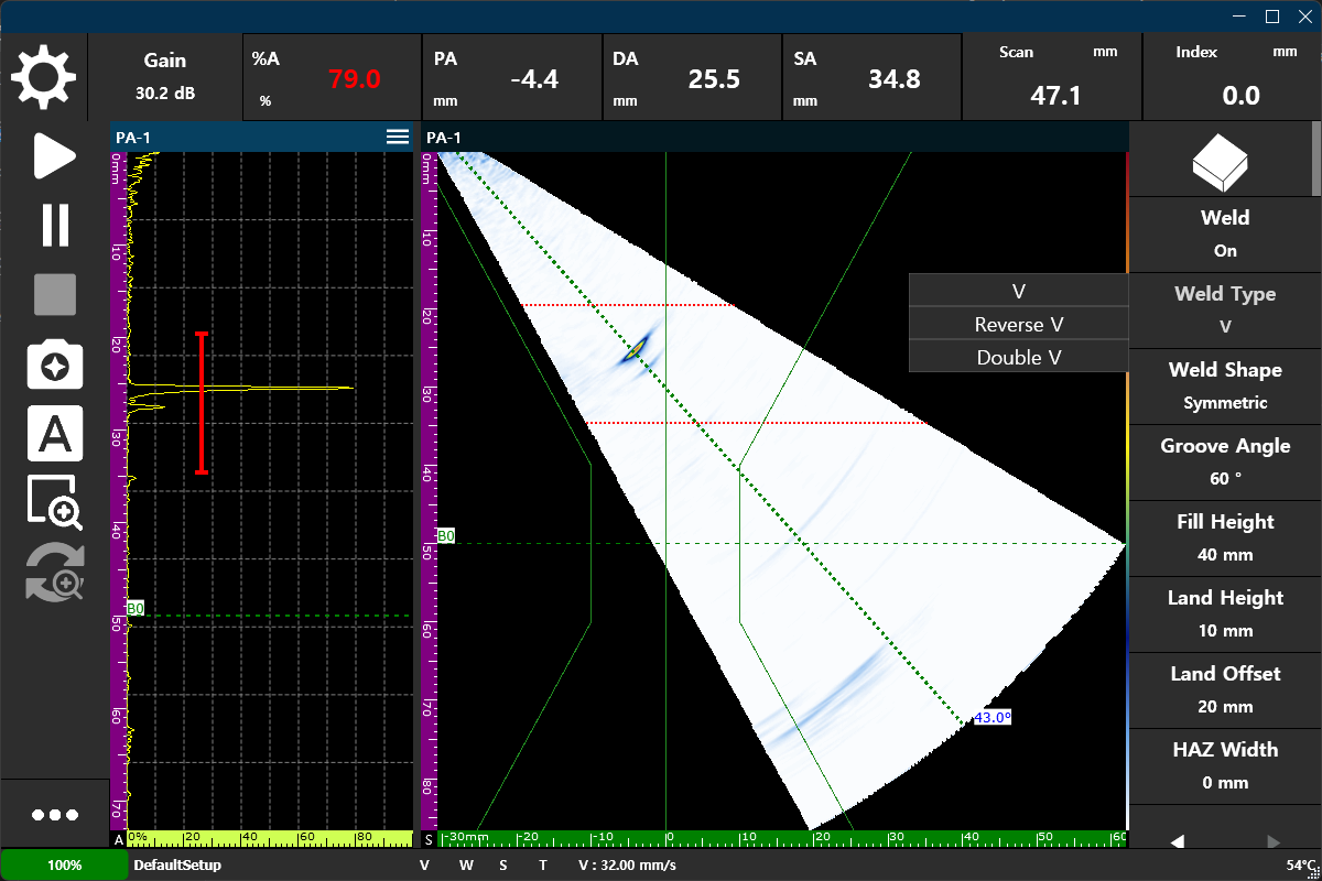
- V-Weld: The standard single-bevel configuration for plate butt joints.
- Reverse V-Weld: Used to align modeling parameters for double-sided welding or inverted specimen conditions.
- Double V-Weld (X-Weld): Implements symmetric double-bevel weld profiles on thick plate materials.
- Asymmetric configurations: Features a Flat Left/Right toggle to model weld prep geometries where one side has a bevel and the other side remains flat, as well as other complex joint shapes.
2. Precision Control of Geometric Parameters
To minimize weld overlay alignment errors, DSVision provides detailed dimensional inputs matching actual engineering drawings.
② Shape Parameter Control Guide
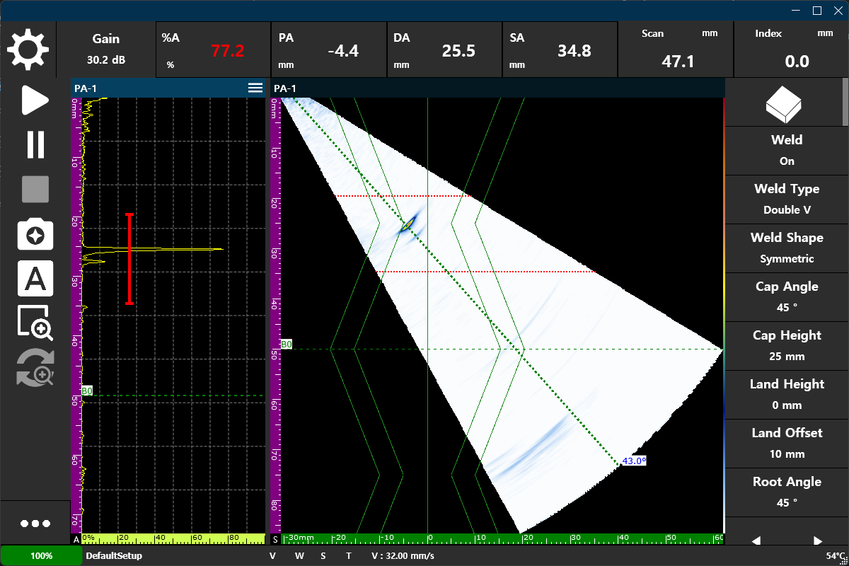
- Groove Angle: Sets the bevel angle of the weld preparation, enabling the ray tracing engine to accurately calculate and predict ultrasonic beam reflections off the fusion lines.
- Fill Height & Land Height: Controls the weld reinforcement (cap) height and root face (land) height to align the overlay with the physical joint dimensions.
- Land Offset (Root Gap): Represents the gap between the root faces, maximizing diagnostic accuracy for root defects (root cracks, lack of root penetration, etc.).
- Heat-Affected Zone (HAZ) Visualization: Lets the inspector define the width of the HAZ bounding box, helping map micro-cracking and material degradation along the weld fusion boundary.
3. Practical Value for Buyers and Inspectors
| Key Feature | Operational Impact |
|---|---|
| Real-time Overlay Update | Dynamic updates reflect dimensional changes on the S-scan instantly, preventing input errors and alignment offsets. |
| HAZ Boundary Marking | Identifies Lack of Fusion (LOF) defects instantly by aligning echo signals with the fusion boundary. |
| Symmetric/Flat Toggle | Adapts to asymmetric joints without physical probe re-orientations, saving scanning time. |
[!IMPORTANT] “Is this defect signal inside or outside the weld?”
When asset owners ask for proof of a defect’s location, DSVision allows inspectors to export reports with integrated Weld Overlay graphics. This provides clear, visual evidence, proving that “the signal is located exactly 1.5mm to the left of the bottom root face of the weld bead.”