DEEPSOUND P5 Product Manual
- Hardware Version: v3.0.5
- Manual Version: v1.0
- Release Date: 2026-04-29
- Last Updated: 2026-04-29
- Author: SEONGSANLAB Co., Ltd.
PART I: Safety and Maintenance
1.1 Safety Information
- This device consists of precision electronic components and high-voltage pulser circuits. Please read the following safety instructions carefully before use.
- Using an external power supply that does not meet the specifications may result in system circuit damage or fire hazard.
- Exercise caution as strong impact, dropping, or excessive vibration can adversely affect the alignment and connection status of internal components.
- There are no user-serviceable parts inside the device. Unauthorized disassembly will void the free repair service.
- Maintain a dry environment when using the device; using it in high humidity or splashing water poses a risk of short circuits and electric shock.
- Do not use probes or adapters with damaged cables during inspection.
1.2 Maintenance of the Device
- Operating Temperature: Recommended range is 0°C to 60°C. Avoid extreme temperature conditions.
- Storage Temperature: Store in an environment between -20°C and 80°C. A cool place away from direct sunlight is recommended.
- If the device is not used for more than one month, remove the battery and store it at a state of charge around 50%.
- Do not leave the device for long periods near large electric motors or transformers that generate strong magnetic fields or electromagnetic interference (EMI).
- Use the dedicated carrying case to protect the device from external impacts during transportation.
1.3 Cleaning Guide
- Screen Cleaning: Use a soft, lint-free dry cloth to clean the 12.1-inch touchscreen. For severe contamination, use a small amount of alcohol-based dedicated cleaner.
- Port Management: Exercise extreme caution to prevent liquids, abrasives, or foreign objects from entering probe connection ports such as TC-ZIF and IPEX.
- Dust Removal: Regularly remove dust around external input/output ports using a non-contact air spray.
- Case Cleaning: Wipe the external housing with a soft cloth slightly dampened with neutral detergent. Do not use chemical solvents or strong abrasives.
PART II: Product Overview
2.1 Introduction to DEEPSOUND P5
- DEEPSOUND P5 is a high-performance portable Phased Array Ultrasonic Testing (PAUT) device designed for precision non-destructive testing in industrial fields.
- Its integrated structure provides high field mobility, and its high-specification hardware enables real-time data processing and high-resolution imaging.
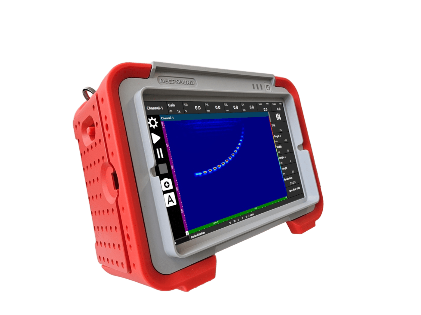
DEEPSOUND P5 Front View
2.2 Hardware Characteristics
- Display: Equipped with a 12.1-inch large touchscreen for excellent visibility. It features a pressure-sensitive method, allowing operation even while wearing gloves.
- Channel Configuration: Supports 32:128PR (Parallel Receive) channel configuration, performing precise ultrasonic beamforming by controlling up to 128 elements.
- Data Processing Speed: Supports a digitization rate of 100 MHz, enabling precise data acquisition without signal distortion even when using high-frequency probes.
- High-power Pulser: Supports variable transmission voltage from 25 V up to 160 V, ensuring stable signals in thick specimens or highly attenuative materials.
- High-speed Scan Support: Provides a pulse repetition frequency (PRF) range of up to 30 kHz, allowing for inspection without data loss during high-speed scanning using an encoder.
- Next-generation Technology Ready: Built-in dedicated computing hardware for processing TFM (Total Focusing Method) and FMC (Full Matrix Capture) algorithms.
2.3 Accessories and Packages
- The standard package of DEEPSOUND P5 includes the following essential components for immediate field use:
- P5 Main Unit: Main device with PAUT/UT inspection functions.
- Smart Battery: High-capacity lithium-ion battery for long-duration outdoor inspection (supports a 3-slot system).
- Power Adapter and Power Cable: Adapter set for device power supply and battery charging.
- Calibration Certificate: Official document containing device performance and calibration data.
- Dedicated Hard Case: Portable hard case with built-in foam to protect the device from impact and moisture.
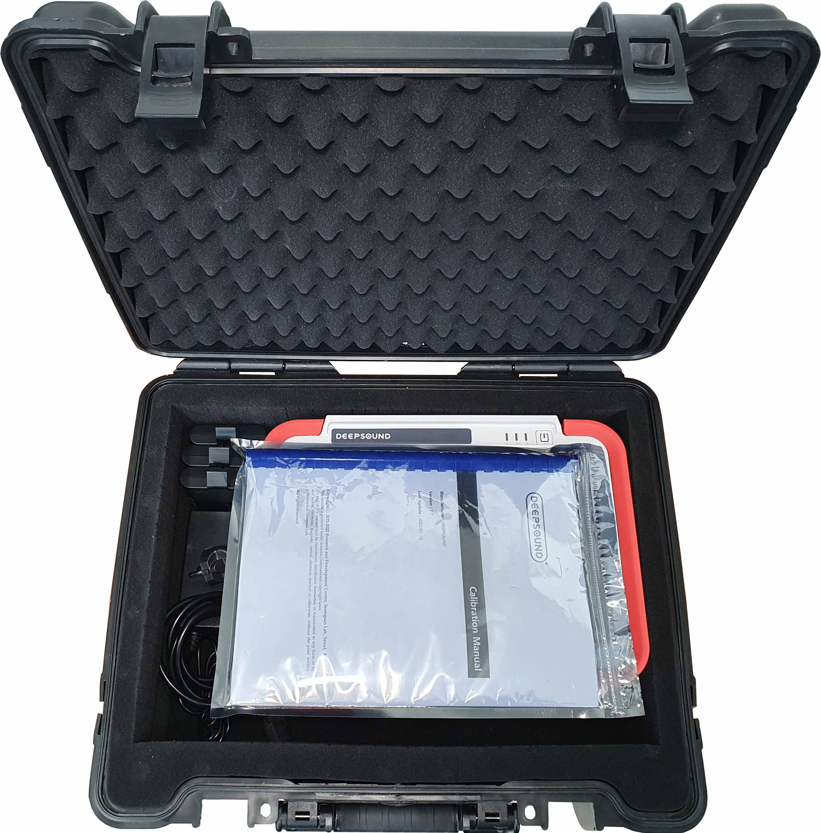
DEEPSOUND P5 Standard Package and Dedicated Case
PART III: Hardware Interface
3.1 Device Layout and Parts
- For field inspection convenience, DEEPSOUND P5 places major input/output ports on the sides and concentrates power and status indicators at the top.
3.1.1 Front View
- Display: The 12.1-inch large touchscreen occupies most of the front, and all operations are performed through software icons without a separate physical keypad.
- Protective Frame: Equipped with a robust rubber bumper frame to protect the main unit from external impacts.
3.1.2 Side Interface (Connector Panel)
- Input/output ports for high-speed data transmission and sensor connection are located on both sides of the DEEPSOUND P5.
[Left Side]
- Probe Port (IPEX 160p): High-density interface for connecting the latest Phased Array probes.
- Encoder Port (D-sub 15pin): 3-axis encoder connection port.
- UT Port (BNC x 2): BNC connectors for conventional ultrasonic and TOFD inspection.
[Right Side]
- DC Input: Dedicated power adapter connection port.
- Ethernet (RJ45): Port for PC communication and network data transfer.
- USB 2.0: Port for connecting external storage devices and peripherals.
- HDMI: Port for external monitor output.
3.1.3 Rear View
- Battery Slots (3-Slot System): There are three independent battery installation slots on the rear of the device, supporting a hot-swap function that allows battery replacement without shutting down the power.
3.2 Control Buttons
- Power Button: A physical button located at the top right of the device that controls system power. The power icon is engraved on top for intuitive identification.
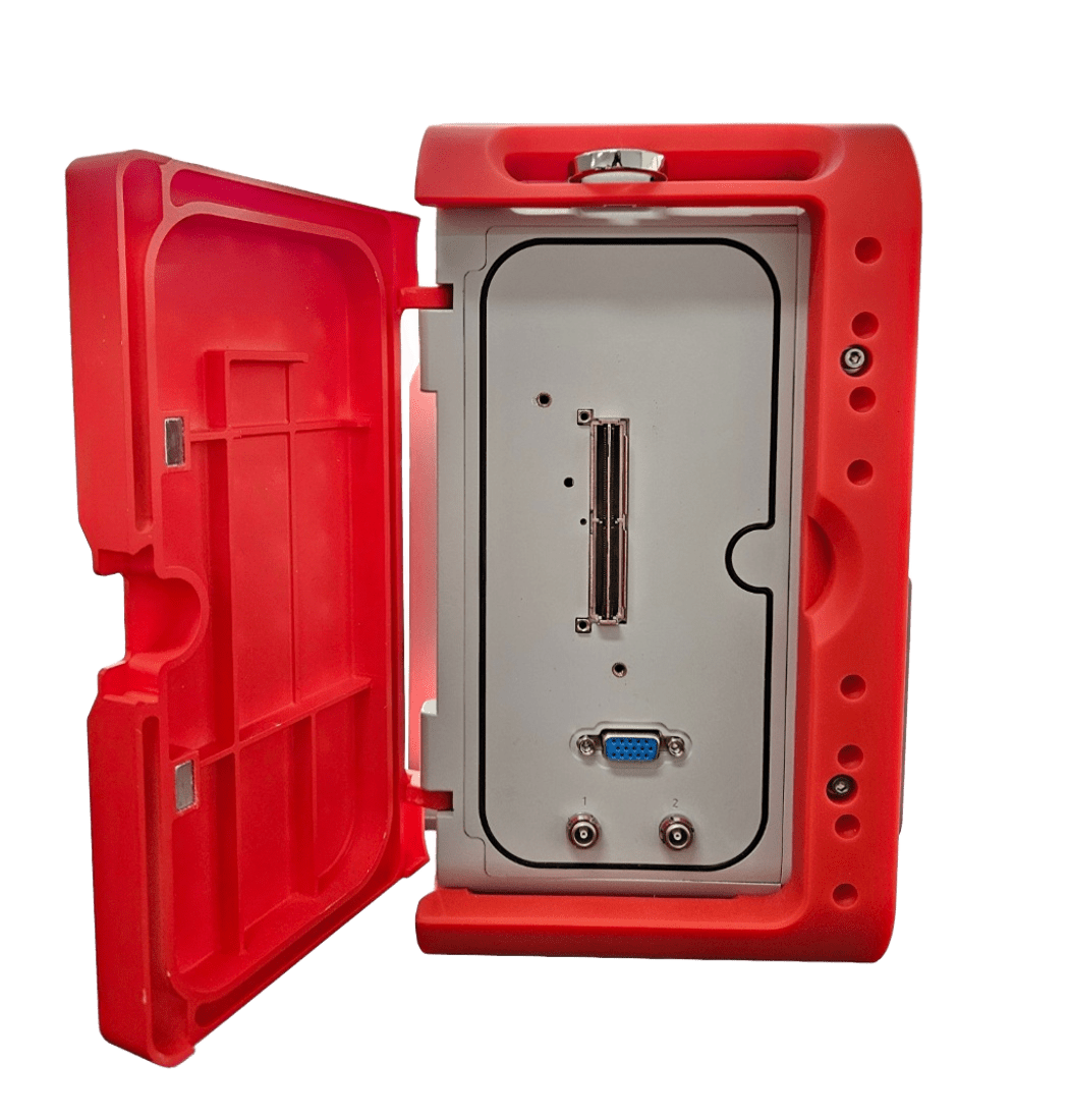
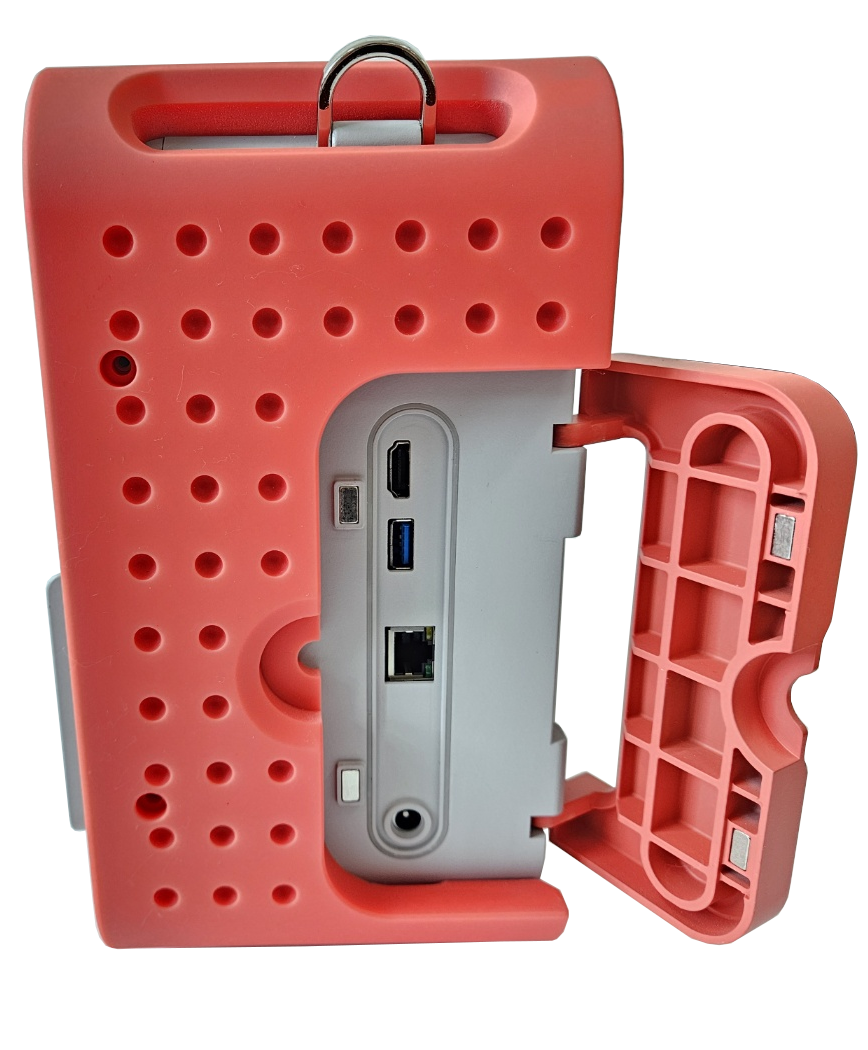
DEEPSOUND P5 Left/Right Side Major Ports and Interface Configuration
3.3 LED Indicator Status
- Three vertical LED indicators (1, 2, 3) representing system status are located to the left of the power button on top of the device.
- LED 1 (Power/Charge): Indicates external power connection and charging status.
- LED 2 (System/Status): Indicates the operating status of the operating system and inspection software.
- LED 3 (Battery): Indicates the remaining battery level and low power warning status.
PART IV: Preparation for Use
4.1 Batteries and Power Management
- DEEPSOUND P5 features high-capacity lithium-ion batteries and an efficient power management system for long-duration field inspections.
- Battery Specification: Uses 48 Wh capacity smart batteries (such as RRC2057) with built-in indicators to check the remaining level.
- 3-Slot System: Provides a total of three battery installation slots on the rear, allowing for long-duration operation without power connection when fully occupied.
4.2 Installing and Charging the Battery
- Battery Installation: After checking the terminal direction of the battery, push it into the rear slot until it “clicks” into place.
- Battery Charging: Open the protective cover on the side of the device and connect the power adapter to the DC power input port. When power is applied, the charging status can be checked via the LED indicators on top.
4.3 Hot-swappable Function
- This device supports a hot-swap function, allowing batteries to be replaced without turning off the system power.
- While at least one battery with sufficient charge is installed, replace the discharged battery in another slot with a new one.
- Caution: Removing all batteries from all slots simultaneously will immediately cut off power and may result in data loss.
4.4 Turning ON/OFF the Device
- Turning ON: Press and hold the power button at the top of the device for approximately 2-3 seconds. The inspection software will automatically run after the system loads.
- Turning OFF: Click the shutdown icon within the software menu, or short-press the power button and select ‘Shut Down’ from the confirmation window that appears.
- Forced Shutdown: In an emergency where the system does not respond, press and hold the power button for more than 10 seconds to force the power off.
PART V: External Connections
5.1 Probe Connections
- DEEPSOUND P5 can connect various Phased Array (PA) and conventional ultrasonic (UT) probes depending on the inspection purpose.
5.1.1 Phased Array Probe (IPEX 160p)
- Connection Method: Align the probe connector with the port and insert gently until the locking mechanism is fully engaged.
- Caution: Always check for foreign objects before insertion to protect the connector pins.
5.1.2 Conventional UT Probe (BNC)
- Insert the BNC cable into UT port 1 or 2 at the bottom of the device and turn clockwise to secure.
- Configuration for single crystal or dual crystal (pitch-catch) probes can be done within the software.
5.2 Encoder Connector (Receptacle)
- Specification: D-sub 15pin 3row Receptacle.
- Function: Connects a scanner equipped with an encoder to collect inspection position (Index/Scan) information.
- Pin Configuration: Supports up to 3-axis (X, Y, Z) encoder signals and 5 V power supply.
5.3 Other I/O Port References
- Opening the dedicated protective cover on the side of the device reveals the following general-purpose I/O ports:
- Ethernet (RJ45): Supports wired network connection with an external PC and high-speed data transmission.
- HDMI: Allows real-time output of the device screen by connecting to an external monitor or projector.
- USB 2.0: For connecting USB memory sticks for data backup or input devices such as a mouse and keyboard.
- DC Input: Connect the dedicated power adapter (15 V ~ 19 V DC) to charge batteries or power the device.
PART VI: Device Specifications
6.1 General Specifications
- Dimensions (WxHxD): 340 x 257 x 147 mm
- Weight: 5.9 kg (With 3 x batteries)
- Power Supply: 12 V, 5 A
- Batteries: Li-ion, 48 Wh capacity (x3)
- Hot swappable batteries: Yes
- Operation Time: Up to 4 hours
- Display: 12.1” Wide Monitor [1280 x 800], Touchscreen
- Storage: 32 GB, expandable
6.2 Connectivity & Environmental
- Ethernet: Fast Gigabit x 1
- HDMI: x 1
- USB Port: USB 2.0 x 1
- Probe Port: MiniDLP Ipex 160p connector x 1
- UT Port: Lemo 00 UT Connector x 2 (for IPEX model)
- Encoder Port: 3-axis Encoder input (D-sub 15pin 3row)
- Operating Temperature: 0 ~ 60 °C
- Storage Temperature Range: -20 ~ 80 °C
6.3 Technical & Acoustic Specifications
6.3.1 PA/UT Configuration
- Effective Digitizing: 100 MHz
- Max PRF: 30 kHz
- Refresh Rate: 30 Hz
- A-scan Height: 300 %
6.3.2 Phased-Array
- PAUT Channel Configurations: 32:128PR
- Scan Type: Linear, Sectorial, Conventional, TOFD
- Focal Law: Up to 1024 total
- Channel Group: Up to 8
- Focusing Mode: True-depth, Sound path
6.3.3 Data Specifications
- Maximum Number of A-scan Data Points: Up to 16,384
- Rectification: RF, Full wave
- Filtering: Selection of Low-pass, Band-pass, High-pass
- Video Filtering: Smoothing
- TFM Raw Data Export: Yes
6.3.4 Acoustic Specifications
- Pulser (Voltage): 25 V ~ 160 V (5 V Step)
- Pulser (Pulse Shape): Bipolar Pulse
- Pulser (Pulse Width): 50 nsec ~ 2,000 nsec
- Receiver (Gain Range): 0 dB ~ 90 dB
- Receiver (Band Width): 0.5 ~ 20 MHz
- Receiver (Sample Resolution): 16 bit
- Dynamic Sample Focusing: Yes
PART VII: Troubleshooting
7.1 Basic Troubleshooting
- If the following problems occur during device operation, please check the following items before requesting technical support.
7.1.1 Power and Battery Related
- Device does not turn on: Check if the battery is sufficiently charged or try again after connecting the external power adapter. Perform a forced reset by pressing and holding the power button for more than 10 seconds.
- Poor battery recognition: Remove the battery from the slot and re-insert it. Check for foreign objects on the battery terminals and wipe them with a dry cloth.
7.1.2 Display and Interface
- Touchscreen not responding: Remove any foreign objects or moisture from the screen surface. If symptoms persist, reboot the device.
- Unable to output to external monitor: Check the HDMI cable connection and ensure the external monitor’s input source is set to HDMI.
7.1.3 Sensors and Data Acquisition
- Probe recognition error: Check the connection status of the IPEX connector. Ensure the connector is fully inserted and secured, and check the probe cable for any external damage.
- Unstable encoder signal: Check if the fixing screws of the D-sub 15pin connector are tightened. Ensure the scanner’s encoder wheels are in close contact with the specimen surface and rotating correctly.
7.2 Error Handling and Support
- If the problem is not resolved after the above measures or if hardware damage occurs, do not disassemble the device arbitrarily and contact the manufacturer.
- Manufacturer: SEONGSANLAB Co., Ltd.
- Address: Room 1318, 13th Floor, Ace High-Tech City, 52, Gongdan-ro 140beon-gil, Gunpo-si, Gyeonggi-do, South Korea
- Phone: +82-2-2039-5725
- Email: admin@dspaut.com